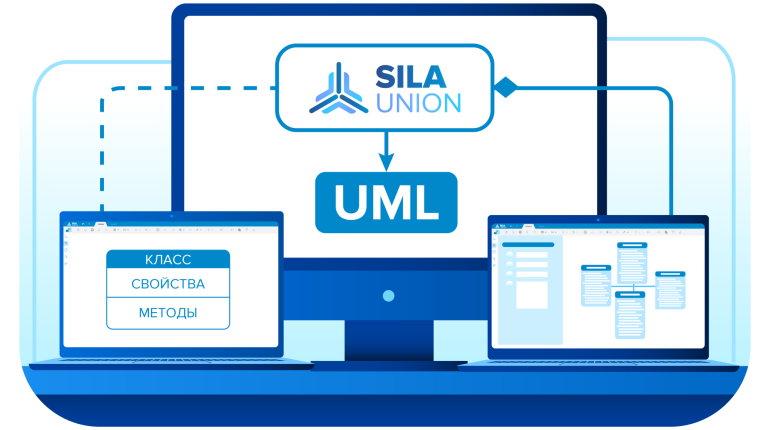
UML in SILA Union: A Key Tool for Effective Business and IT Design
UML (Unified Modeling Language) is a standardized graphical modeling language that helps visualize, design, and document information systems. Its key feature is broad applicability: UML is used not only in IT but also in business analysis, customer journey design, and process description.
In SILA Union — a digital platform for integrated business architecture, IT architecture, and process modeling — UML plays a vital role by providing:
A unified communication language between clients, analysts, and developers, eliminating the risks of miscommunication.
Visualization of complex structures, simplifying the design and optimization of business processes.
Flexibility and scalability — UML is not tied to a specific programming language and is especially effective with object-oriented approaches.
Automated documentation, speeding up development and reducing the risk of errors.
By using UML diagrams, SILA Union users gain a powerful tool for system analysis, digital solution design, and organizational process optimization.

In this article, we’ll cover:
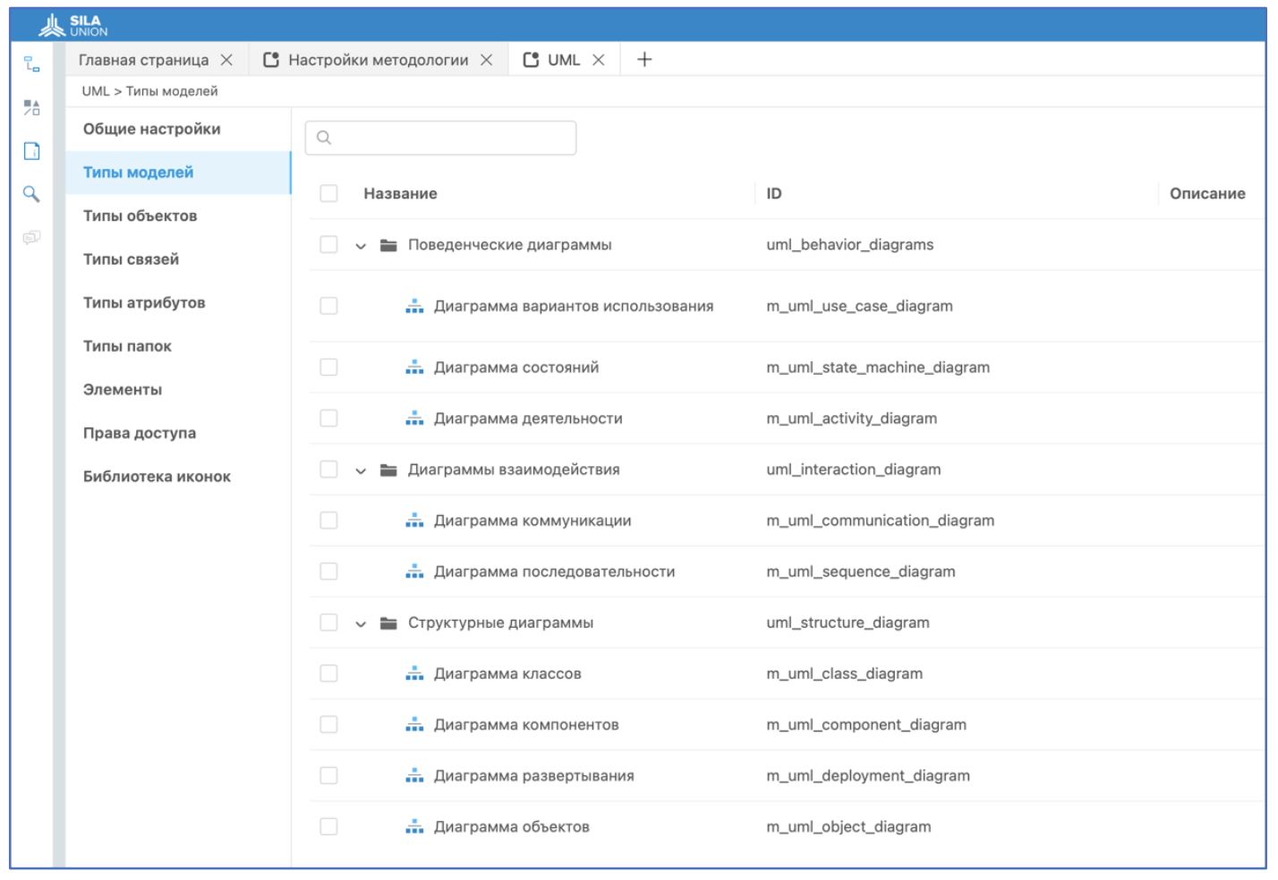
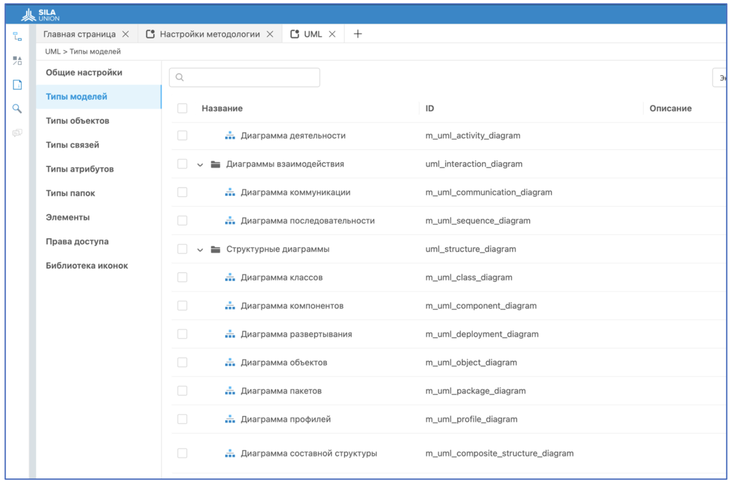
The 12 types of UML diagrams available in SILA Union and their use in business and IT modeling.
Practical examples of diagram creation with step-by-step instructions and visuals inside the SILA Union system.
Discover how UML in SILA Union helps turn complex architectural challenges into clear and manageable models.
UML Diagram Types in SILA Union
SILA Union features 12 UML diagrams that serve various functions. Some describe system structure, others system behavior, and others still the interaction of components (see Figures 1–2).
Structural Diagrams
Structural diagrams show the static architecture of a system, its components, and their relationships:
Class Diagram – The most common UML diagram, illustrating system structure through classes, attributes, methods, and relationships (association, inheritance, aggregation, composition).
Object Diagram – Shows instances of classes and their relationships at a specific moment.
Component Diagram – Displays physical system components (libraries, modules, executables) and dependencies.
Composite Structure Diagram – Shows the internal structure of a class and its ports/connectors.
Deployment Diagram – Illustrates how components are deployed on physical hardware (servers, processors).
Package Diagram – Groups related elements (classes, interfaces) into packages to simplify large systems.
Behavioral Diagrams
Behavioral diagrams represent the dynamic aspects of the system — how objects interact, change state, and execute processes:
Use Case Diagram – Describes system functionality from a user's perspective (actors and use cases).
Activity Diagram – A flowchart showing step-by-step process logic.
State Machine Diagram – Shows object state transitions in response to events.
Interaction Diagrams
A subtype of behavioral diagrams focused on communication and message flow:
Sequence Diagram – Displays time-ordered interaction between objects.
Communication Diagram – Focuses on object relationships rather than message order.
Timing Diagram – Shows changes in object states on a timeline (real-time systems).
Interaction Overview Diagram – Combines elements of activity and sequence diagrams to give a high-level scenario overview.
Each diagram type serves a distinct purpose and is used at various project stages — from requirements analysis to detailed design.
Creating UML Diagrams in SILA Union: Examples and Description
Class Diagram
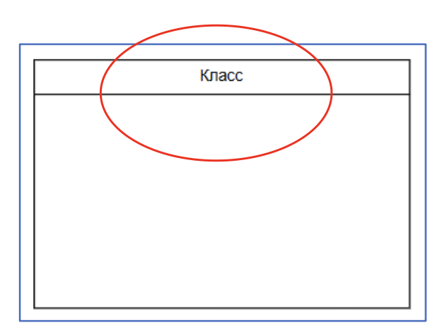
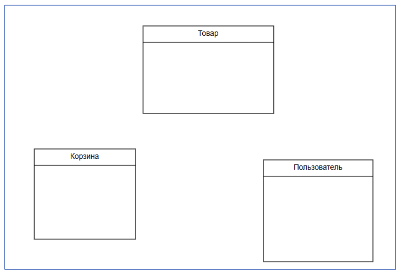
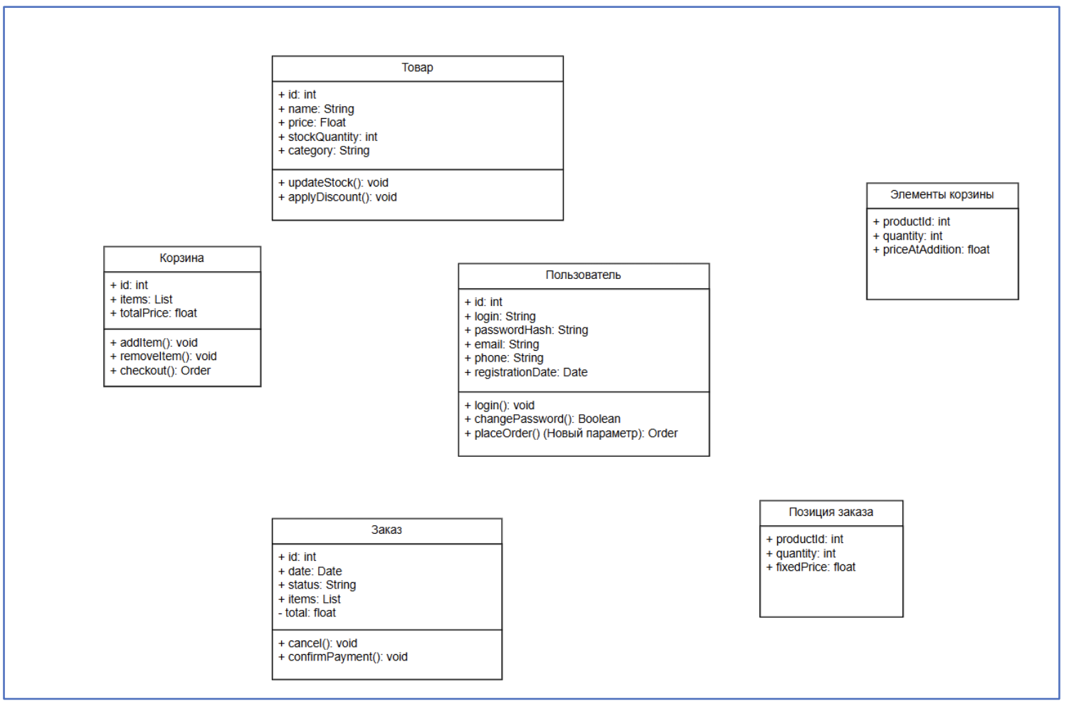
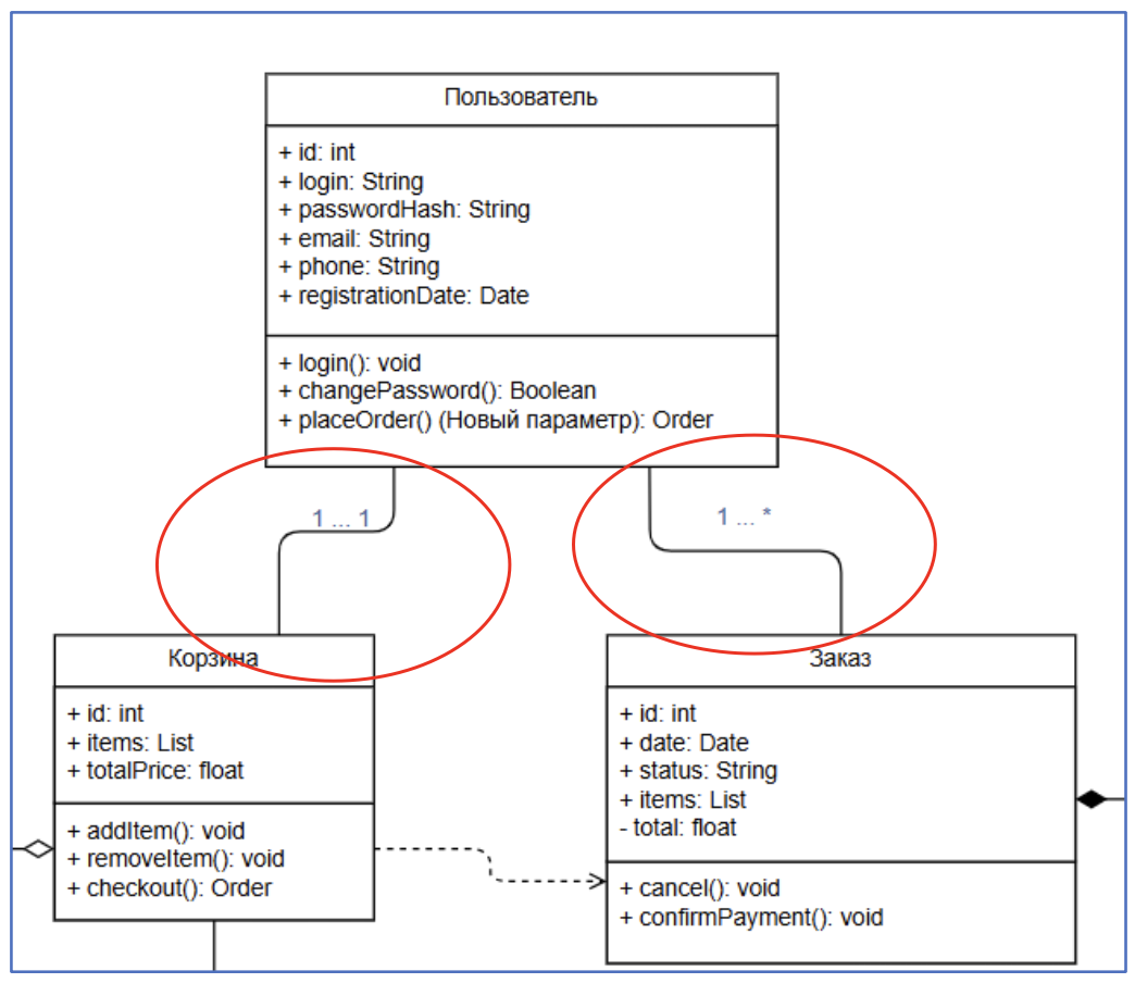
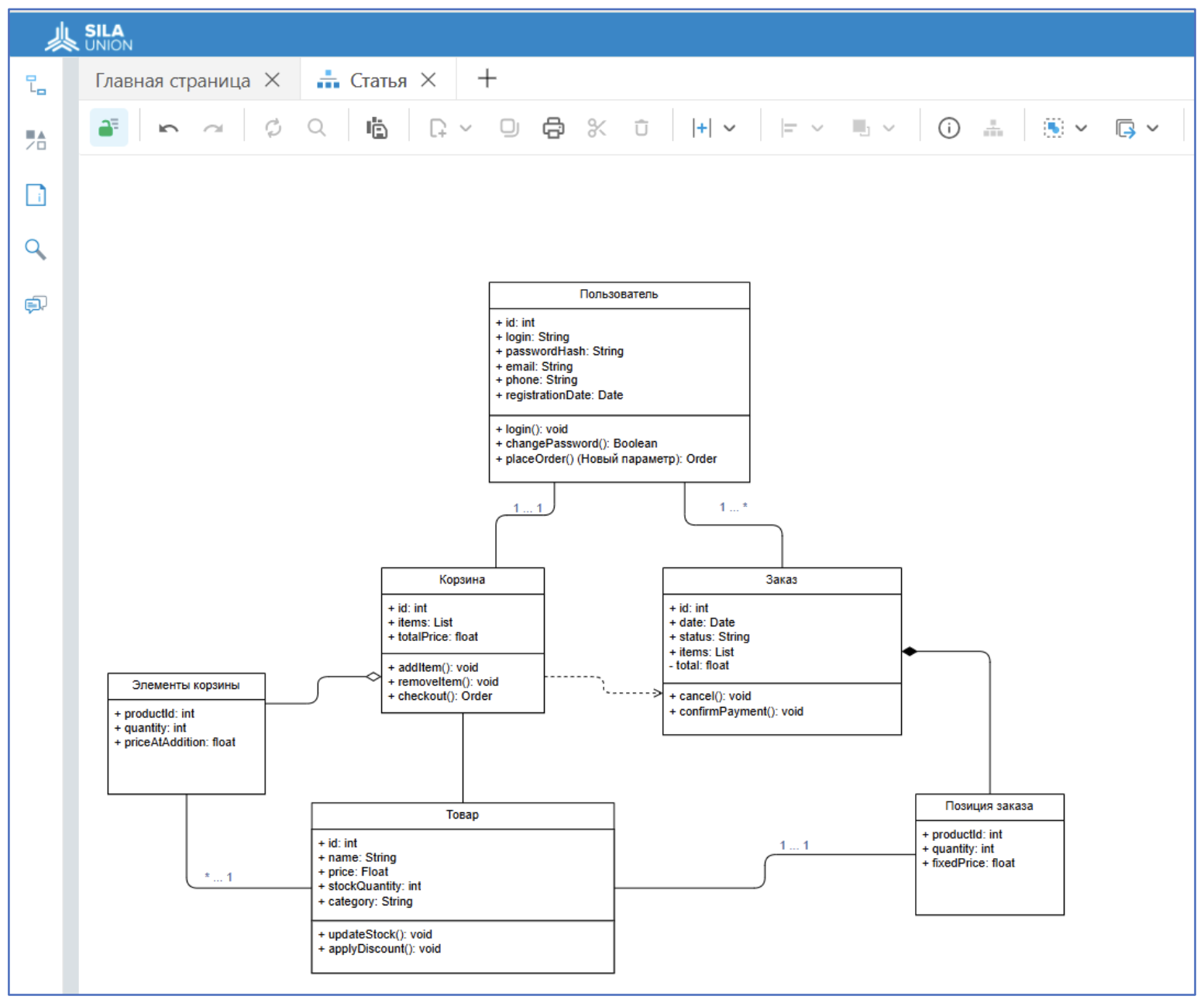
A class diagram explains what components make up a system. For example, in an e-commerce platform: Product, Cart, User, and Order classes might be used — each with fields (like price or quantity) and methods (like "add to cart"). This forms the foundation for designing the database and backend logic.
Class = template describing structure/behavior
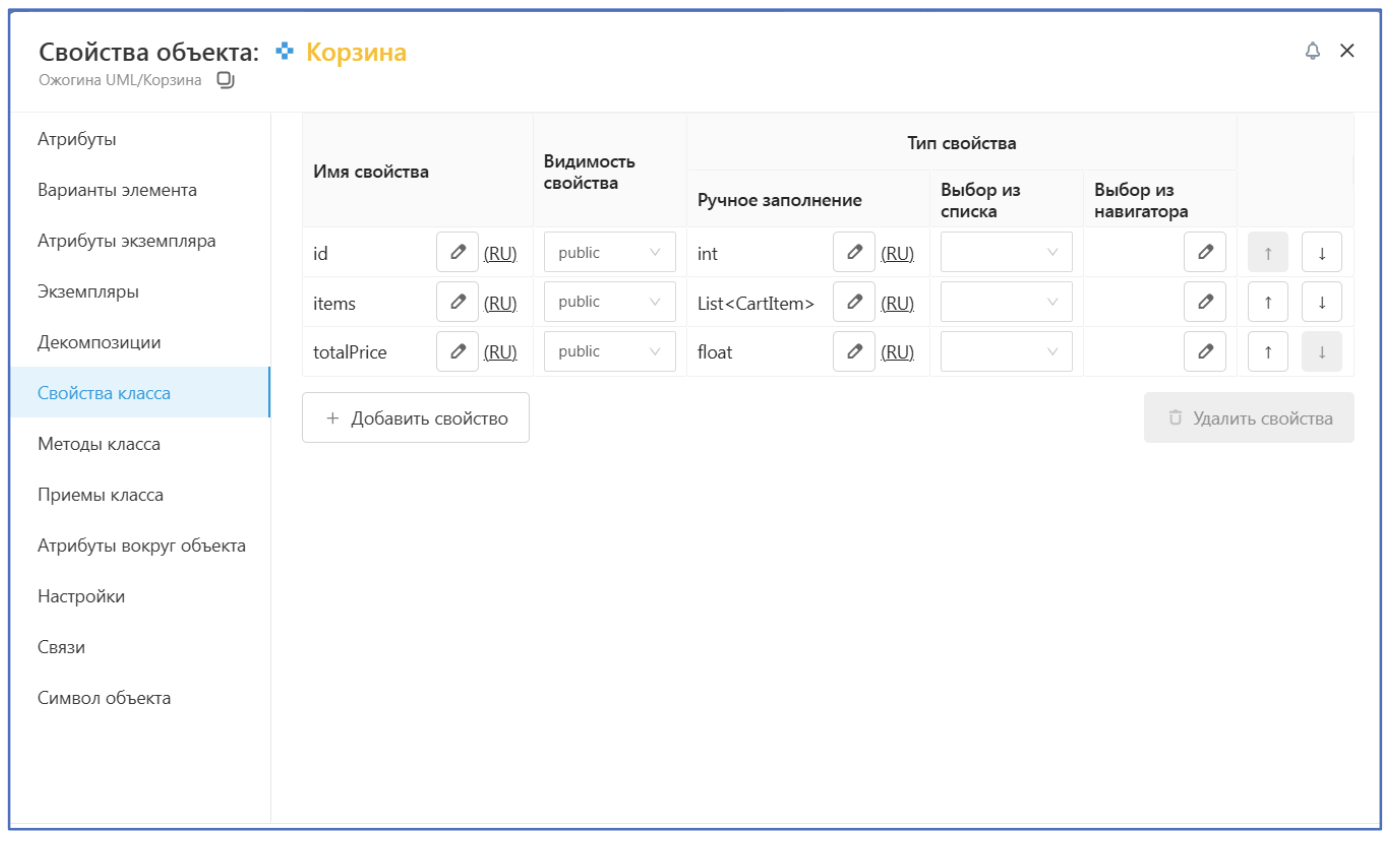
Attributes = data held by an object
Methods = actions the object can perform
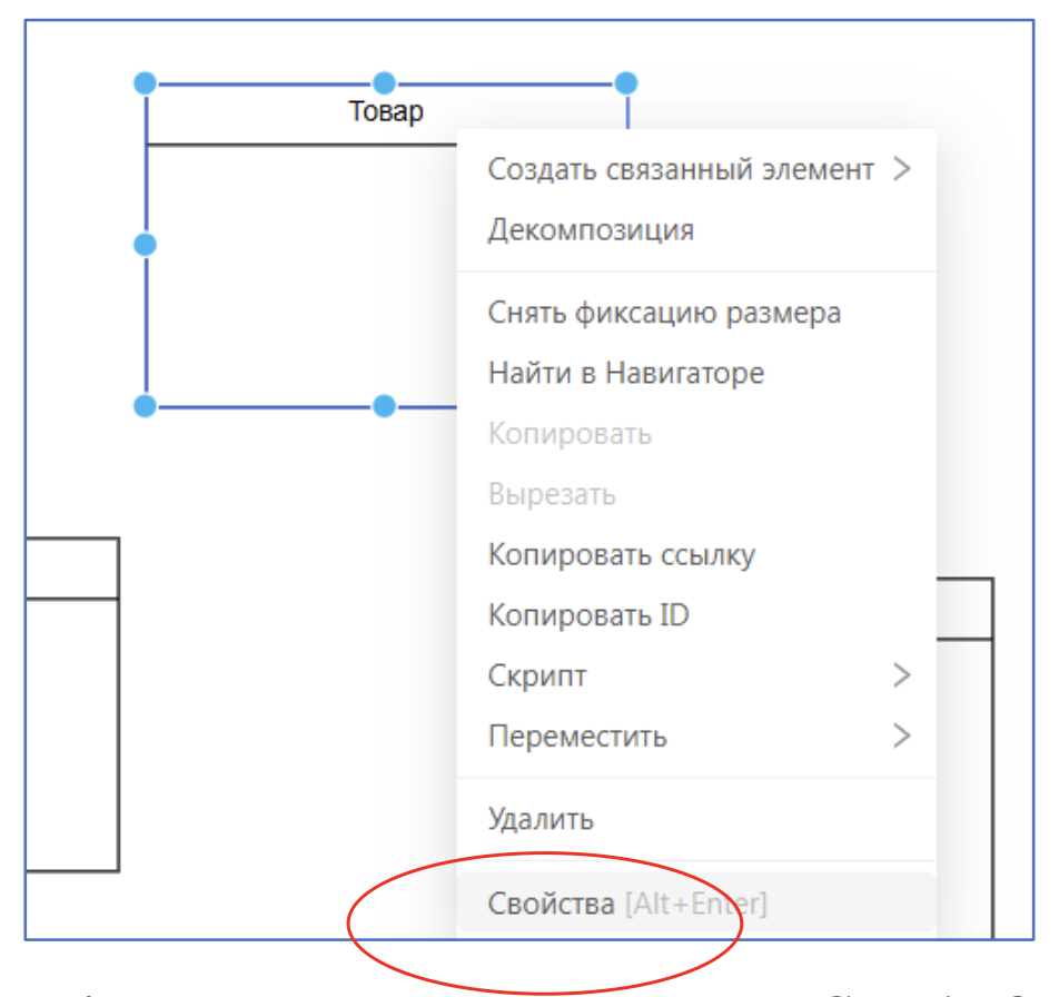
SILA Union allows step-by-step creation of such diagrams, including adding properties, methods, and relationships between objects.
Association (1:1) – e.g., User has one Cart
Association (1:many) – e.g., User can have many Orders
Aggregation – e.g., Cart contains CartItems, which can exist independently
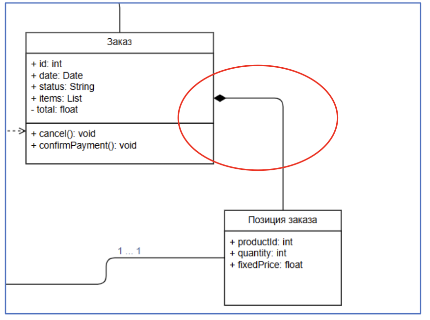
Composition – e.g., Order contains OrderItems, which depend on the Order
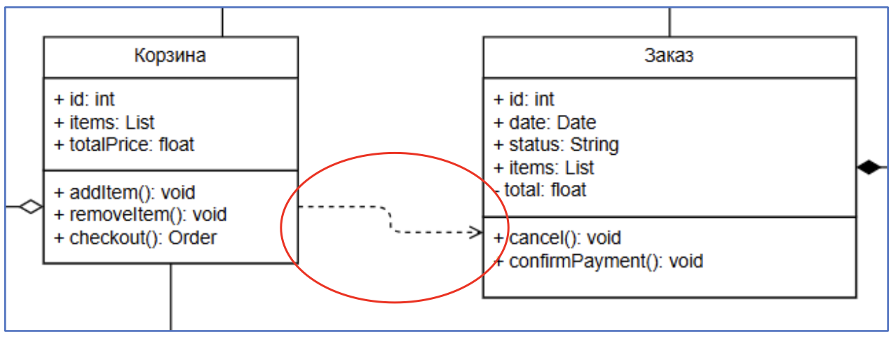
Dependency – e.g., Cart relies on Order to complete the process
These relationships form a complete model of how components interact logically and structurally.
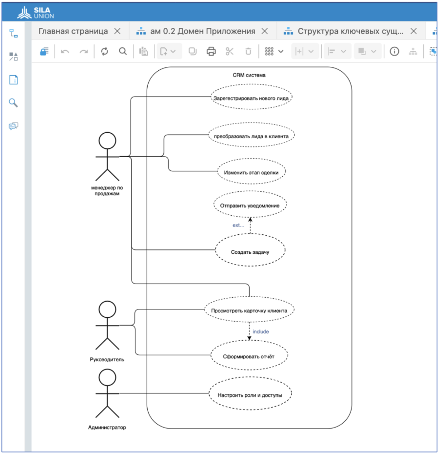
Use Case Diagram
This diagram shows who (actors) and how (use cases) interact with the system.
Actor = user or external system
Use Case = function the system performs
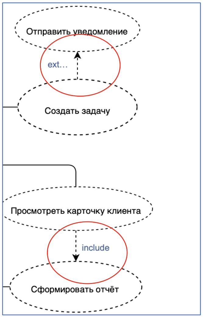
Includes/Extends = represent mandatory or optional actions
Example: In a CRM, a Sales Manager registers a lead, the Admin configures system settings, and the Director oversees KPIs — all illustrated in one diagram for clarity.
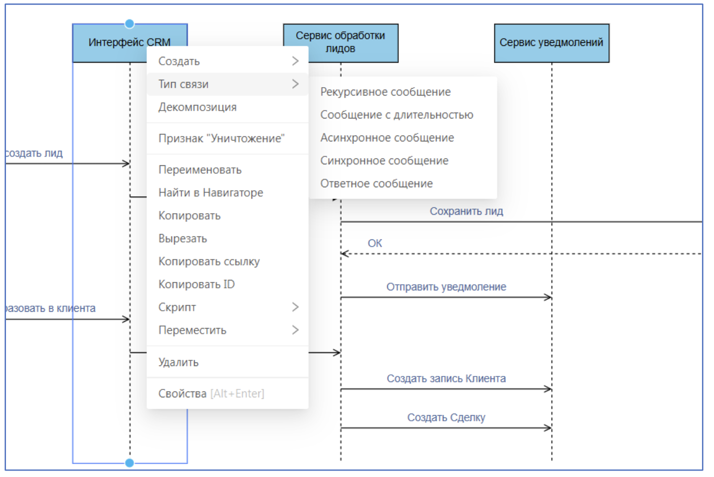
Sequence Diagram
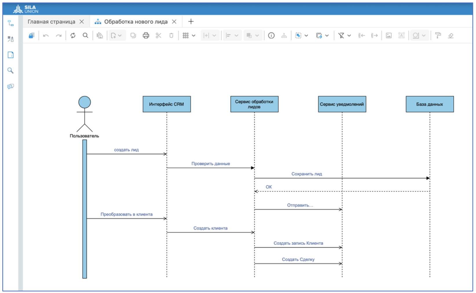
Represents message flow over time between system components. For example, a CRM workflow:
Sales Manager creates a new lead.
CRM system forwards data to lead validation service.
Data is validated (completeness, format, duplicates).
A new record is stored in the database.
Notification system alerts relevant employees.
The lead is qualified, converted, and a deal is created.
Each message is ordered vertically, reflecting real-time logic. Arrows represent:
Synchronous message – sender waits for reply
Reply message – return from a call
Asynchronous message – sender doesn’t wait
Message with duration – time gap between sending and receiving
Self-message – object calls itself
This diagram serves as a bridge between business analysts and developers — ensuring alignment on logic and execution.
Conclusion
UML is a practical tool for understanding complex systems, communicating ideas, and avoiding early-stage errors. Each diagram addresses a specific task, and together they provide a complete system overview — both structurally and functionally.
SILA Union leverages UML not only for designing processes but also for standardizing development, improving team communication, and speeding up digital transformation. With UML, you can adapt diagrams to your exact needs — from high-level architecture to detailed business process flows — reducing miscommunication across project stages.
Thus, UML remains a foundational element in the development and analysis of complex systems, offering clarity, flexibility, and reliability. Its universality makes it indispensable for both technical and business professionals, proving its relevance in modern digital platforms like SILA Union.
Want to see how UML can improve project management and accelerate digital transformation? Explore the capabilities of SILA Union and start modeling your business processes today. For recommendations on using UML in your projects, contact us at sales@silaunion.ru.


